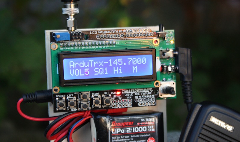
The ArduTrx Shield with an Arduino and a display board mounted in a self made wooden case. Completed with a 2S lipo battery, an antenna and a Kenwood-compatible hand mic ready for its first QSO.
The ArdTrx project consists of two parts: the ArduTrx shield and the software. Both parts can be used independant from each other.
The ArduTrx shield is an Arduino shield with a HF module and surrounding circuitry. The shield plugs directly into the pin header of the Arduino Uno or compatible board and forms a stack with it. Other shields can be plugged on top or in between.
The ArduTrx software utilizes this shield but could also be used with a compatible HF module on a breadboard. To get a useful HMI it is suggested to plug a SainSmart 1602 LCD Keypad Shield (https://www.sainsmart.com/products/lcd-keypad-shield-for-arduino-duemilanove-uno-mega2560-mega1280) on top.

The hardware is built around the popular HF modules from Dorji or NiceRF and utilizes all necessary circuitry to get the module running and audio in and out of it.
A HF module from Dorji or NiceRF is used on the shield. 2 meter (144 MHz) or 70 centimeter (440 MHz) modules can be soldered.
Unfortunatelly these HF modules produce spurious emissions. Therefore a HF filter is implemented on the shield. It is a chebyshev low pass filter and has a cutoff frequency of 185 MHz.
The HF modules allow a maximum voltage of 4.5 V (Dorji) or 5.5 V (NiceRF). Arduinos usually don't provide these voltages. But you only get the maximum HF power if you go to the voltage limits. Therefore ArduTrx uses a adjustable power regulator LT1085. The desired voltage can be set with the resistors R15 and R17. Additionally the modules draw up to 750 mA while transmit. This is too much for the voltage regulators on the Arduinos. The LT1085 on the ArduTrx shield can provide up to 3 A.
To make the audio output of the HF module hearable you need a speaker and an audio driver. ArduTrx shield uses a LM4871 which is optimal for battery powered circuits with low voltage and can drive high power with its differential output. The speaker can be connected to CN6. It is also possible the drive single ended loads like head phones on CN4.
ArduTrx can be used with 3.3V and 5V arduinos and these level shifters guarantee the right voltage level on the transmission lines.
The rotary encoder is only connected to the pins of the arduino and has no connection to the HF module. It can be used in Arduino programs to set the frequency of the HF module.
The HF module needs a serial input from the arduino to change its configuration. Unfortunatelly this serial port of the Arduino is also used during programming of the Arduino and generates programming errors if it is also connected to HF module. So ArduTrx has a switch to open the serial connection to the HF module and allow programming (switch in off position). The switch has to be turned on if settings to the HF module have to be made.
This connector has the same function as the coaxial power connector on the Arduino board. It only uses an industrial connector and allows a safer connection. The input voltage can be measured with R35 and R36.
The antenna connector is a SMA connector like it is used on many Hand-helds.
CN3 and CN4 form a hand mic connector which is compatible to Kenwood or Baofeng.
| Arduino pin | direction on Arduino | usage |
|---|---|---|
| 0/RX | input | serial communication with HF module Attention: also used for programming the Arduino |
| 1/TX | output | serial communication with HF module Attention: also used for programming the Arduino |
| 2 | input | squelch. low=RX active; high=no RX |
| 3 | output | analog / pwm audio output; for example for 1750 Hz tone. |
| 4 | - | not used |
| 5 | - | not used |
| 6 | - | not used |
| 7 | - | not used |
| 8 | - | not used |
| 9 | - | not used |
| 10 | - | not used |
| 11 | output | PTT: low=no TX (RX); high=PTT active |
| 12 | output | Power down: low=sleep mode; high= normal mode |
| 13 | output | Output power: low=1W; high=0.5W |
| A0 | - | not used |
| A1 | input | measurement input for VIN or serial input of GPS |
| A2 | input | audio input to Arduino |
| A3 | input | rotary encoder signal A |
| A4 | input | rotary encoder signal B |
| A5 | input | rotary encoder switch |
| AREF | - | not used |
| SCL | - | not used |
| SDA | - | not used |
| RESET | - | not used |
| IOREF | - | reference voltage for level shifters (U4 and U5) |
| VIN | - | input voltage for voltage regulator (U2) |
| 3.3V | - | not used |
| 5V | - | supply voltage for CN5 (GPS connector) |
| GND | - | GND |
| Designator | Package | Quantity | Value / Manufacturer and Partnumber | order numbers | ||
|---|---|---|---|---|---|---|
| Reichelt | Farnell | other | ||||
| C1,C4 | C_0603 | 2 | 30p | KEM C0G0603 30P | 2627466 | |
| C13 | C_0603 | 1 | 1u | KEM X5R0603 1,0U | 1759039 | |
| C15 | c_elec_8x10.5 | 1 | 470u | HA-V 470U 16 | 9695710 | |
| C2,C3 | C_0603 | 2 | 47p | KEM C0G0603 47P | 1759062 | |
| C5,C7,C8,C10,C11,C12,C14,C16,C17,C18,C19,C20 | C_0603 | 12 | 100n | KEM Y5V0603 100N | 1759122 | |
| C6,C9 | C_0805 | 2 | 10u | KEM X5R0805 10U | 1762635 | |
| CN1 | WR-SMA-PCB | 1 | Wuerth 60312202114509 | RND 205-00509 | 1608592 | |
| CN2 | ARDUINO | 1 | ARDUINO stacked pin header | Conrad 1516613-62 | ||
| CN3 | 1503_07 | 1 | Lumberg 1503-07 | LUM 1503-07 | ||
| CN4 | 1501_03 | 1 | Lumberg 1501-03 | LUM 1501-03 | 1200127 | |
| CN5 | Pin_Header_Straight_1x03 | 1 | CONN_01X03 | MPE 087-1-003 | 1022249 | |
| CN6 | Pin_Header_Straight_1x02 | 1 | CONN_01X02 | MPE 087-1-002 | 1022247 | |
| CN7 | WR-TBL_691322310002 | 1 | Wuerth 691322310002 | AKL 382-02 | 1642012 | |
| D1 | LED_0603 | 1 | Led red | SMD-LED 0603 RT | 2426211 | |
| D2 | LED_0603 | 1 | Led yellow | SMD-LED 0603 GE | 2426218 | |
| D3 | LED_0603 | 1 | Led green | SMD-LED 0603 GN | 2426215 | |
| D4 | SOD-123 | 1 | BAT46W | BAT 46W | 2689977 | |
| L1,L2,L3 | WE-CAIR_4248 | 3 | Wuerth 744912156 | 2431629 | ||
| Q1,Q2,Q3 | SOT-23 | 3 | 2N7002 | 2N 7002 SMD | 2317619 | |
| R1,R6,R7,R8,R10,R14,R16,R24,R25,R26,R31 | R_0603 | 11 | 1k | SMD-0603 1,0K | 2447272 | |
| R12,R13,R21,R27,R2,R33,R34 | R_0603 | 7 | 4k7 | SMD-0603 4,7K | 2447385 | |
| R15 | R_0603 | 1 | 121 | SMD-0603 120 | 2447242 | |
| R17 | R_0603 | 1 | 300 | RND 0603 1 300 | 2447331 | |
| R19,R20,R36 | R_0603 | 3 | 20k | RND 0603 1 20K | 2447293 | |
| R23 | R_0603 | 1 | 2k | RND 0603 1 2K | 2447319 | |
| R3,R9,R11,R18,R22 | R_0603 | 5 | 100 | SMD-0603 100 | 2447227 | |
| R35 | R_0603 | 1 | 100k | SMD-0603 100K | 2447226 | |
| R4,R5,R28,R29,R30,R32 | R_0603 | 6 | DNI | |||
| S1 | dip_1-300 | 1 | SW_DIP_x1 | RND 210-00162 | 1960917 2319976 | |
| SW1 | WE_4312x6xxx7x6 | 1 | TAST_HOR | TASTER 3305 | 1555989 | |
| SW2 | ALPS_EC11E | 1 | ALPS_EC11E | STEC12E08 | 2064990 | |
| U1 | DRA818 | 1 | DRA818 | box73 DRA818V | ||
| U2 | TO-263-3Lead | 1 | LM1085IS-ADJ | 1469038 | ||
| U3 | SOIC-8_3.9x4.9mm_Pitch1.27mm | 1 | LM4871 | LM 4871 M | 1468873 | |
| U4,U5 | SOT-23-6 | 2 | SN74LVC1T45 | 1470916 | ||
DNI means do not install. Leave this part unpoplated.
The software utilizes the ArduTrx shield on any compatible board. Together with an HMI board it creates a complete hamradio transceiver.
You can find the software on github: https://github.com/generationmake/ArduTrx
The software is released under GPL v2
In the source code in line 50 to 52 you have to define which hf module you use.
When you start ArduTrx it will display the version and release date for a few seconds during startup. After that the main menu is displayed.
In the main menu on the first line on the left it shows "ArduTrx". You can change this to your Callsign or whatever you like in the source code in line 48.
In the first line on the right it shows the used frequency. The frequency can be changed by turning the rotary encoder. If there is "-" in front of the frequency an offset for repeater operation is used. it is defined in line 81 to 83 or 90 to 92.
In the second line there are several parameters.
You can change the active point by pushing left or right button. The active value is blinking. You can increase or decrease the value by pushing up or down button.
When you are at M for menu pushing up or down will bring you to the menu. You can skip through the options by pushing left or right. The menu has the following options:
By pushing down the active option can be changed. Then pushing right or left changes the value of the option. Pushing up saves the value and the next options may be changed.
Pushing the select button in the main menu will activate PTT and send a 1750 Hz tone for repeater operation.
Pushing the rotary encoder in the main menu will switch from high to low power and backwards.
PTT is activated by pushing the PTT button (SW1) on the right top or pushing the PTT button on the hand microphone.
Switch S1 has to be closed all the time except during programming.

The fully assembled shield ready to plug into an Arduino board

Close-Up of the display and HMI with keys and rotary encoder

This was the first prototype
| Date | Location | File |
|---|---|---|
| March 3rd 2019 | Make Munich | ArduTrx_Vortrag_makemunich2019.pdf (in German) |
If you have any questions contact me via email at bernhard@generationmake.de, make an issue at github or send me a message at twitter (https://twitter.com/generation_make).
Last update: 30. may 2019